Bubbles the Clown Animatronic
Overview

This project was my senior project for ME 102B Mechatronics Design at UC Berkeley. This project required us to integrate both mechanical and electrical systems. The class of Fall 2020 projects can be seen here, where mine is also featured.
As a child, my family has always been big fans of Halloween which sparked my interest in animatronics. It has even inspired me to become a mechanical engineer. With this old Halloween prop, I took this opportunity to make my own animatronic.
This was done out of pure curiosity in hopes of getting my foot in the door into the animatronics world. One of my favorite projects!!!
You can also see my actual report here.
This project was done during the pandemic, so I was very limited on supplies and tools.
Supplies
-
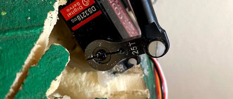
20KG Digital Servo x2 Used for head movement.
-
SG90 Micro Servo Motor x6 Used for jaw and eye movement.
-
Universal Ball and Socket Joint x1 Used for universal movement of the head.
-
Ball Joint Link x4 Used for smoother movement of servo joints.
-
Threaded Rods x2 Used for attaching the servos in the shoulder to the head.
-
Stiff Wire x1 Used to attach the servo to the jaw running through the neck.
-
M3 Screws x40 Used to attach 3D printed parts
-
PLA 170g Used for printing eye components through the Jacobs Support Program offered to students at UC Berkeley during the pandemic.
-
Expanding Foam Used for filling the holes made from the assembly process.
Process

Preparing the Prop
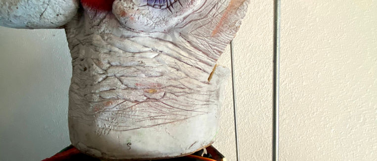
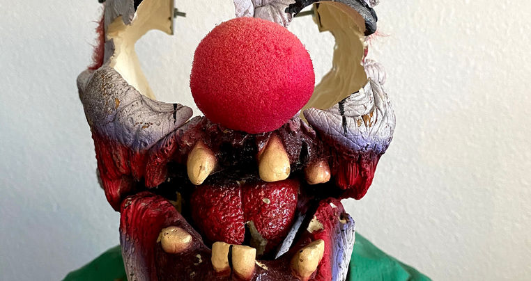
Initially, Bubbles was entirely made out of Styrofoam. So to start, I had to completely empty him out using a Dremel to make room for the electronics.
This was most time consuming along with assembling the eye mechanism. The nice part was that Styrofoam is easy to work with and the prop already had a scary persona, so I didnt have to design an entirely new character.
After everything was assembled into the prop, I covered up all patched with canned foam which can be found at any hardware store.
A little patching up, reshaping, repainting and BAM you got the persona of your animatronic.
Controls
NOTE: I used the ESP32 microcontroller and programmed it through Arduino IDE (code shown below)
All actuations are controlled by a PS4 controller. Using the Arduino IDE I was able to connect the PS4 controller to my ESP32 and control the servos using commands using the controller.

This is actually super easy to implement.
-
Download the PS4-ESP32 library
This is the foundation of connecting the controller to the ESP32. Also contains great examples of how to implement events in your code.
-
Download the SixaxisPair Tool
Using this tool, you'll get your PS4 controllers MAC address in this format: "03:03:03:03:03:03". You will need this MAC address to put into your setup() loop in Arduino so your microcontroller can find your PS4 using Bluetooth.
-
Refer to the PS4RecieveData.ino example
I couldn't figure out how to implement a code snippet here, so just refer to this example on how to implement the controller in your setup() loop with your MAC address in the PS4.begin() command.
Head and Actuation
I took inspiration from Cat Alvord's "How to Animatronic" to implement the servos for the head actuation. The servos were then connected to a threaded rod (any rod can be used) and attached to each side of his head.
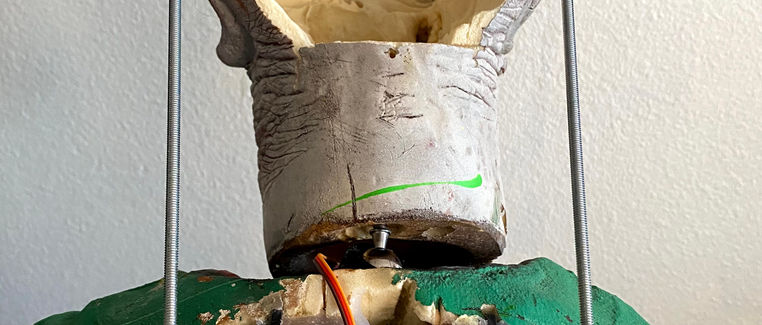
I then mounted his head to a ball and socket joint which was hot glued at the top of his torso. This allows universal movement and minimal resistance as the servos move the head.
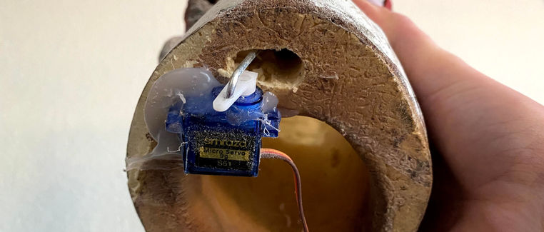
For his jaw, I hot glued a 9kg servo to the bottom of his neck, ran a long stiff wire through his neck and hot glued the wire to the inside of his jaw. This was surprisingly easy and different than Cat's animatronic linked above. The jaw itself was connected to two springs at each side which was apart of his original design (super nice to work with).
Eyes
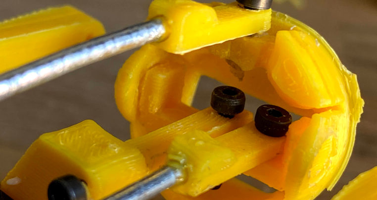
I used Nilheim Mechatronics "Compact and Roboust 3D printed Animatronic Eye Mechanism" design to integrate the eyes. I pulled this 3D CAD, had them 3D printed at Jacob's Maker Space at Berkeley and had them shipped to me (cause you know, pandemic things).
As I was assembling the parts together, none of the prints fit nicely to each other so I spent days filing them down to the right size. These parts were very delicate and broke when filing and snap fitting them together. I had to put in another order last minute.
This was the most annoying part of the entire project since nothing fit together easily and the small parts were soooo fragile.
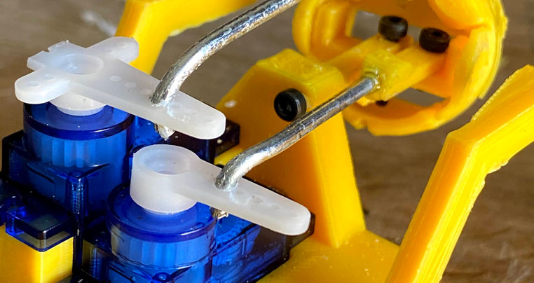
As seen above, I connected the servo horns and the eye mechanism using stiff wire.
Assembly
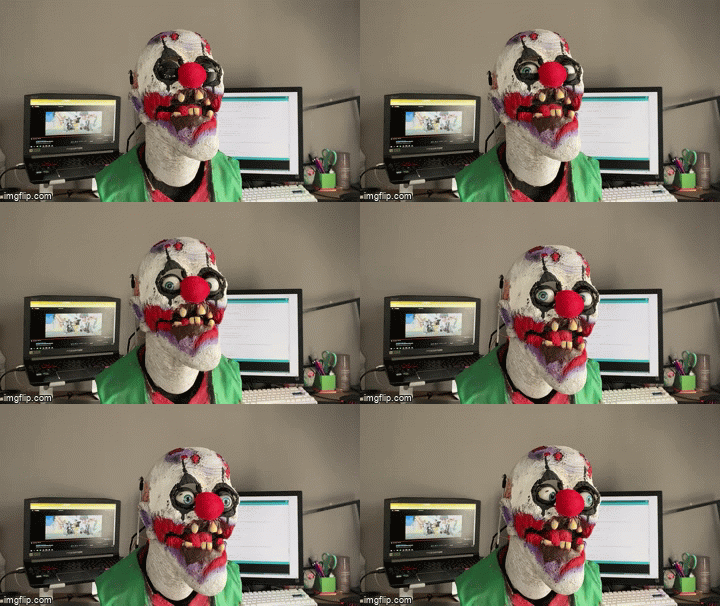
Assembly was almost as annoying as assembling the eye mechanism. It was really difficult to keep the prop in tact as much as possible because I am no artist whatsoever and cannot replicate his details for my life.
With my eye mechanism assembled, all I head to do was slide the mechanism into his head. Thankfully the mechanism was JUST RIGHT to fit his actual eye placement. But getting it in the head was our biggest issue. We had to shave the sides of his head off just the get the mechanism in there. As seen in the pictures above, the eye mechanism is actually standing on toothpicks and hot glued on the sides to stay in place.
Since we removed so much styrofoam using the dremel to insert the eye mechanism, we had to replace all of it using canned foam. Canned foam actually doubles in size when fully cured, so we had to dremel the excess to make him look realistic again.
Circuit Diagram and State Machine

.png)
Code
I couldn't figure out how to implement a code snippet on here, so if you're actually interested you can just download it.
Sorry not sorry ¯\_(ツ)_/¯
