Combat Robot

Overview
I single handedly designed and manufactured a 3 lb combat robot within 3 months with no prior experience.
This was done during my junior year at UC Berkeley with the combat robotics team, RoboBears. With the club I was able to compete at UC Berkeley's Combat Robot Competition. This was one of my first projects I was super proud of and sparked my passion for designing and manufacturing.
After this project, I stepped up and took the role of President of RoboBears, which is now thriving under my administration.

Competition


Round 1
First round my robot fought against UCLA's vertical spinner. I had trouble driving due to the excitement, nervousness and adrenaline rushing through me.
All I can say here is "Go Bears!"
Round 2
Second round I fought against a professional hobbyist who does not have school work and does this in his free time.
With a bashed, half working robot I still managed to flip him (skip to 1:15 in the video).
Even though I lost this round a spectator approached me after the round and said to me "That was very impressive, I have never seen anyone flip his robot like that before"
Supplies
Chassis
-
Top & Bottom Plates
-
Aluminum 0.0125'' thick
-
-
Side & Back Plates
-
HDPE 3/8'' thick
-
-
Drive Motor Mount
-
Aluminum 0.0125'' thick
-
-
Weapon Motor Mount
-
Aluminum 0.0125'' thick
-
Process
Weapon
The weapon is implemented using a belt and pulley system on a dead shaft. The weapon is 3/4'' tool steel with holes added to reduce weight.
The pulley is 0.714:1 ratio using the FingerTech Pulley Calculator
The weapon bar initially had holes installed to allow the red pulley to be screwed onto the bar. The bearing and copper bushing was then press fitted to the center of the pulley. The copper bushing is there at a 'spacer' to the weapon bar can sit at the same height at the motor pulley. Its necessary to note that I had the press fit professionally done.
Finally with the bearing and bushing installed, the weapon shaft slid perfectly in the bushing. As previously mentioned, the shaft is a dead shaft and is held in place by the shaft collars on either side of the aluminum chassis.


Weapon Testing
After hours of building, I finally got the blade to spin.
In this video, I have the throttle at about half speed. Tip Speed: 250 mph.
Excuse my excitement in the excessive zooming.
DO NOT TRY THIS AT HOME.
Chassis


Top & bottom plates were made out of aluminum 0.25'' thick, and cut using OMAX Water Jet Cut at Jacobs Maker Space. Similarly, the drive motor mounts and weapon mount were also made of aluminum, 0.25'' thick.
Spray painted for aesthetics, but next time I would wait until the end to paint because the paint kept scratching.
Assembly


Assembly was smooth for the most part, but I did run into some problems along the way.
First I connected the weapon mount to the weapon and bottom plate of the chassis. The weapon mount was mounted to the bottom of the chassis plate because the weapon motor was too high and the motor pulley was not at the same height of the weapon pulley. Further, I forgot to account for the wires at the bottom of the weapon motor, so I had to make space by drilling a hole (big headache). Another mistake I made with the weapon motor was that I did not account for the 'clip' at the bottom of the weapon motor. That 'clip' actually spins with the motor since its an out runner, so I had to drill another hole so it could freely spin.
I then installed the drive motors and their mounts to the side plates secured with locking nuts. Ideally, the locking nuts should be inside the chassis to prevent play with the wheels but here I had no choice and had to move them to the outside. This subassembly was then screwed into place to the bottom plate of the chassis.
Next I installed the weapon shaft with the weapon. The weapon shaft came in 12'' so I had to cut it down to the appropriate size and add flats using the vertical grinder. The flats are necessary because the set screws in the shaft collars need a flat surface to hold on to. When using the vertical grinder please do not use your hands because the shaft will get very hot.
Here was my biggest obstacle: the belt had too much slack when installed onto the pulleys. I was given two options: create slots in the bottom plate to give the weapon motor to slide back, or create a tensioner. Neither of these solutions were easy, so I made a tensioner that consisted of two bearings that sat in between each pulley. This was very successful.
During testing, the motor later burnt out on me due to not having enough torque to spin the 1.5 lb blade. I later had to replace the motor with a 1400kv brushless motor to fix this problem. I also had to redesign the motor mount because of the replacement motor.
Electronics
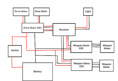
At the time, I was not very familiar with electronics so I had my friend help me with the circuit diagram.
Surprisingly, the wires took up more space than I accounted for, so I had to be careful with how much wires I used. I did eventually have the issue of spacing of all electronics. I had to make sure that nothing touched the weapon motor because it was an out runner and could easily destroy all my electronics if safety was not ensured. This was fixed by cutting all wires shorter and resoldering all electronics (biggest pain in the butt).
The electronics were held down with Velcro and taped down with electrical tape, which all worked fine.
The ultimate flaw to my entire design: electronics were not protected. This ultimately led to my demise and costed me a loss in the competition. In my last round, I ran into the wall with my weapon causing the shaft to deflect and hit my internal electronics which I was unable to fix. Lesson learned: PROTECT YOUR ELECTRONICS.
Final Assembly
The final assembly was indeed overweight but I was able to cut it by taking out some screws and drilling holes in random places to cut the weight.
When I finally finished the assembly, I remember being soooo proud of myself and I was happy as a chicken :)
